Thread replies: 364
Thread images: 73
Thread images: 73
Anonymous
/ohm/ - effay edition 2016-09-28 00:16:55 Post No. 1061668
[Report] Image search: [Google]
/ohm/ - effay edition 2016-09-28 00:16:55 Post No. 1061668
[Report] Image search: [Google]
last thread >>1050981 →
tp://pastebin.com/9UgLjyND
>I'm new to electronics, where do I get started?
There are several good books and YouTube channels that are commonly recommended for beginners and those wanting to learn more, many with advanced techniques. The best way to get involved in electronics is just to make stuff. Don't be afraid to get your hands dirty.
>What books are there?
Beginner:
Getting Started in Electronics Forrest Mims III
Make: Electronics Charles Platt
How to Diagnose and Fix Everything Electronic Michael Jay Greier
Intermediate:
All New Electronics Self-Teaching Guide: Kybett, Boysen
Practical Electronics for Inventors: Paul Scherz and Simon Monk
Advanced:
The Art of Electronics by Paul Horowitz
>What YouTube channels are there?
https://www.youtube.com/user/mjlorton
https://www.youtube.com/user/paceworldwide
https://www.youtube.com/user/eevblog
https://www.youtube.com/user/EcProjects
https://www.youtube.com/user/greatscottlab
https://www.youtube.com/user/mikeselectricstuff
https://www.youtube.com/user/AfroTechMods
https://www.youtube.com/user/Photonvids
https://www.youtube.com/user/sdgelectronics
https://www.youtube.com/user/TheSignalPathBlog
>What websites feature electronics projects or ideas?
http://adafruit.com
http://instructables.com/tag/type-id/category-technology/
http://makezine.com/category/electronics/
>Where do I get components and lab equipment from?
digikey.com
jameco.com
sparkfun.com
ramseyelectronics.com
allelectronics.com
futurlec.com
ladyada.net/library/procure/hobbyist.html
mouser.com
alliedelec.com
newark.com
ebay.com
>What circuit sim software do you use?
This mostly comes down to personal preference. These are the most common ones though:
NI Multisim
LTSpice
CircuitLab
iCircuit for Macs
>What software should I use to layout circuits?
Circuit Wizard
ExpressPCB
EAGLE
KiCad
>>
File: Nodal_voltages_question.png (108KB, 723x789px) Image search:
[Google]

108KB, 723x789px
I asked about this a couple of days ago on last thread, and now that I am doing it I am confused no how to solve this one.
Using nodal analysis, I am unsure if I wrote the correct equations since the position of Voltage V2 in the middle kind of confuses me. I dont know if its affect all of the resistors in that part (R4, R5, R6) or if I should just consider it for R4, R5 and R3.
>>
File: supernode.png (54KB, 640x672px) Image search:
[Google]

54KB, 640x672px
>>1061777
This is also another one I wanted to ask on.
I know that theres a supernode up there, but I am unsure as how to consider that current there which is parallel to the voltage source. Is it going out of the supernode?
My intuition tells me that it goes out but then it goes... back into it? But I maybe talking out of my ass.
I did those equations but, then again, would like some insight.
>>
>>1061777
Almost. The last term for V1 should have V1-V3 not V1+V3, and the second term for V2 should have V2-V1 not V2-V4.
The equation for the current at a node (by KCL) will only refer to the impedances of the edges incident to that node (i.e. R3,R4,R5 for V2).
Thus, the values of R1,R2,R6 will only affect V2 via their effects upon V1,V3. I.e. the KCL equation for V2 won't refer to R1,R2,R6, but solving the system of equations will give a value for V2 in terms of E1,I1 and all 6 resistances.
>>
>>1061784
A supernode is a group of nodes where the total current sums to zero. It's an extension of KCL from a single node to an arbitrary group of nodes (given that the total current into any one node is zero, the total into any collection of nodes must also be zero: 0+0+0+...=0).
The two nodes in question have both the voltage and current source between them (i.e. the current source should be inside the red loop).
The 3A current source changes nothing other than the current through the 16V battery. If you don't need to know that current, you can just remove the 3A current source.
So:
V1/R1+V2/R2=4A (KCL at supernode)
V2=V1+16 (PD across supernode).
=>V1=48V, V2=64V
=> I(R1)=48/20=2.4A, I(R2)=64/40=1.6A
IOW, there's 2.4A flowing from right to left through the supernode. If you apply KCL at the two actual nodes, you find that there's 5.4A "charging" the battery (i.e. the 2.4A net current through the supernode plus the 3A circulating within it).
>>
File: Clipboard01.png (2KB, 446x296px) Image search:
[Google]
2KB, 446x296px
>>1061784
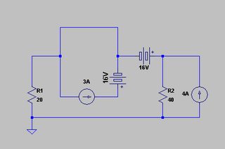
Another way to handle such cases is to move the voltage source forward through the node, as in pic.
This effectively removes the current source from the problem. Once you've solved it, you'll find that there's 2.4A through once "instance" of the voltage source and (clearly) 3A through the other, giving 5.4A total.
>>
File: 1414458420348.jpg (5KB, 200x200px) Image search:
[Google]

5KB, 200x200px
I drive a newer car and the Dash warning lights are surface mount LEDs instead of the traditional twisty bulbs. I want to disable one in particular, the light that warns you that traction control is off because I really don't need to be reminded all the time that I turned it off considering I have a device that turns it off everytime I start the car. Anyway, instead of just desoldering the LED, can I run a jumper wire or resistor or something to make the current want to bypass the LED? Basically I want to disable it but don't want to take it off in case I lose it.
>>
>>1062444
just paint over the spot where it lights up
>>
>>1062451
mmm nah
>>
>>1062454
depends on how it's wired up then lad.
>>
>>1062456
as far as what?
>>
>>1062458
as far as if you can remove it or need to replace it with something.
>>
File: 1375259661945.jpg (8KB, 400x481px) Image search:
[Google]

8KB, 400x481px
>>1062459
>>
>>1062460
post the circuit diagram lad
>>
>>1062466
there isnt one sadly. does this help? its from someone else changing the led colors.
>>
>>>>1062478
simplest way is to cover it with some plastic doodad, like the cap from a marker, and scotch tape it in place. if you have the skills you can cut the trace leading to it, or solder 3 series diodes in parallel with it. the 3 diodes will drop the voltage across the LED to 2.1V so it wont have enough voltage to light. you could simply short it, but that might overheat a chip or something.
>>
>>1062530
i think im just going to forgo the bullshit and just replace it with a regular diode so it has the draw and drop without the light to minimize potential problems
>>
>>1062536
a diode drops 0.7V whereas an LED will drop 1.7V for red, around 2.2V for green and yellow, 3-4V for blue and white.
and if you have the skills to replace it, then you have the skills to just remove it. no need to replace it with anything.
>>
>>1062478
You can probably just jumper it with some wire, the circuit is already prepped with a resistor, so jumping it shouldn't cause any issues.
That said I'd just desolder it.
>>
>>
>>1062444
find the led and measure its forward drop,
parallel it with something with a slightly lower forward drop, like a small zener or some diodes in series.
say its forward drop is 2 volts and you put a 1.5v zener in parallel, the voltage would never go above 1.5v and the led would never light.
its probably just current limited with a resistor, so you could probably just short it, but this way the current stays mostly the same .
>>
Those of you who etch prototype pcbs, what setup do you guys use to drill through holes? I'm trying to improve my pcb making process and my traces have officially gotten too small to use a hand drill...
>>
File: 1374982334347.jpg (46KB, 538x717px)

46KB, 538x717px
>>1061668
i have an old pc psu i made into a power supply and one of the things i want to use it for is an adjustable and regulated power supply for laser diodes. can someone give me a resource for how to make a circuit that have adjustable current and voltage output that is regulated so it doesnt spike and kill the diode?
>>
>>1063113
nevermind i think i found something on amazon that is infinitely better than what i could cobble up
>>
>>1063113
A boost converter can be either constant-voltage or constant-current. For a constant-voltage supply, you want a filter capacitor across the output. For a constant-current supply, you don't. Other than that, it's just a matter of measuring voltage or current for the feedback (also: for high currents, you want a low reference voltage to minimise power dissipation in the sense resistor).
But laser diodes above 10mW or so need constant beam power, i.e. you need to monitor the beam intensity and adjust the diode current accordingly.
The difference between the threshold current (above which the diode emits light) and the maximum current (above which the diode will be permanently damaged in less than a microsecond) is less than the amount by which those two levels vary with die temperature.
The other issue is because even very short pulses of excess current will damage the diode, you need to ensure that there aren't any power-on transients. Regardless of whether the current regulator is linear or switching, the main thing is to ensure that the pass transistor doesn't have significant series capacitance.
>>
File: circuit1.jpg (95KB, 854x810px)

95KB, 854x810px
Would this kind of thing work okay as an h-bridge driver? (A and B being microswitches)
>>
File: atx-power-supply-connectors.jpg (69KB, 561x443px)

69KB, 561x443px
I have no USB chargers in my household - I have never needed to power anything over USB 5V that could utilise more current than whatever my PC's usb ports could supply, which I presume is 500mA.
There is a USB power bank that I need charged quickly - I just soldered a USB typ A female connector onto an ATX PSU's 5V rail (which is capable of 20A), and plugging the powerbank into it shows that it charges since the powerbank's lights go on.
However upon measuring the actual current draw using the 10A range on my meter, it shows a current draw of only 330mA.
What could be the deal here? Is there some communication that usb-powered devices perform with their chargers to enable higher current draws? Voltage of the 5V rail is steady at 5.12V.
>>
File: 20160929_225300.jpg (2MB, 3264x2448px) Image search:
[Google]
2MB, 3264x2448px
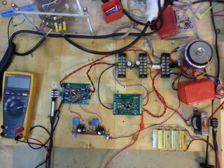
work so far.
-set up a power supply with resistors and caps to decouple screen and preamp supply from output pentode supply.
did it very much by the book and didnt experiment much aside from using the same supply for the screen and preamp,
probably wont make much of a difference as both of those only bull a few mA each.
used a 4p16p, russian military equivalent of el84
-set up simple single ended output stage, measuring all voltages, bias currents and plate/screen dissipation to get a better understanding of how it works.
slightly adjusted the cathode resister for a colder bias, but it was very slight and not really necessary to begin with.
-then i set up a rudimentary preamp with a dual triode, 6n2p(similar to 12ax7)
both stages are identical and probably designed for clean guitar.
i skipped the tonestack and just used two 1meg 'volume' pots.
this means that i can feed it more than its intended to take since there is no tonestack loss, making it sound terrible if i crank both pots.
I can get mild distortion that sounds okey, but not great.
-I reduced the bias resistors by adding 2ks in parallel to the 1k5 in place. giving me a hotter bias that distorts more easily, but still not great.
its no secret that only two stages isn't good for anything but the mildest break up.
-I elevated the heater to ~35v, removing most of the heater noise.
in a proper chassis this thing would be deathly silent due to the low gain. but I'm not really interested in a low gain 5w amp, this is just experimentation.
-the cathode bypass and decoupling caps are quite big(25µF and 250nf respectively), so the bass response is a bit over the top.
i might try to mess with these values and see if i can get a more balanced sound, but I'm really more motivated to try a more interesting preamp topology next.
i have built a couple of tube amps before, but I was mostly just following schematics.
this way i learn more.
>>
File: 20160929_224158.jpg (2MB, 3264x2448px) Image search:
[Google]

2MB, 3264x2448px
its interesting to look at the scope while playing.
here its a single string ringing out, being all smooth and shit.
>>
File: 20160929_225142.jpg (2MB, 3264x2448px) Image search:
[Google]
2MB, 3264x2448px
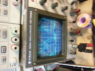
here you can see a hard strum clipping on the low side but not the high due to the hotter bias.
the phone isn't very fast so it picks up multiple lines on the scope, but you get the idea.
taking a pic of the scope while picking is surprisingly difficult.
>>
How does /ohm/ store their components?
A binder full of baseball card pages seems to be a good method, but I'd like something interesting.
>>
File: 51SaSUnaPNL._SY300_.jpg (20KB, 300x300px)

20KB, 300x300px
>>1063298
stick with the industry standard
>>
File: 20160929_223912.jpg (2MB, 3264x2448px)

2MB, 3264x2448px
>>1063297
uhh, why did 4chin rotate my pic?
anyway, here is one of the preamps I'm eager to test.
the pentode input stage and led biasing is interesting.
http://www.ax84.com/static/corepreamps/Blues/AX84_Blues_Preamp_Schematic.pdf
i main source of info is the valve wizards preamp book, which has some interesting toplogies and design methods for many preamps.
i think that might be next after the blues amp, unless i feel the need to make a pushpull poweramp before then.
if i ever get to the point of having a gig, i must have a scope on stage.
>>
>>1063292
the charger inside the powerbank might not be suited to handle any more than that, its made for usb after all.
>>
>>1063292
there is some voodoo involved, however this usually involves the charger waiting for the go-ahead to deliver more current. your power supply has no such safeguards, so you're stuck. is it possible you hooked it up to the +5V-standy pin? another possibility is that the battery is near fully charged and is just topping up.
https://en.wikipedia.org/wiki/USB#USB_Battery_Charging
>>1063272
both circuits should do the job assuming the OP-AMPS can supply enough current to switch the transistors ON hard.
>>1063298
little plastic baggies, like for drugs, with individual values, stored in plastic drawers by decade, (1K-9K, 10K-99K, etc)
>>
>>1063302
I'd love to have one of these and automate it
>>
File: PreampSchematicV5.jpg (72KB, 1023x491px)

72KB, 1023x491px
>>1063304
again, I'm going to use a russian equivalent in place of the 7199
>>
I'm going to EE studies at Monday. Is it good to invest some money on electronics or should I go for arduino kit's for learning both electronics and programming which I will have too.
>>
>>1063427
Arduino is great to start with, be sure to move on to "clean" AVR's after few months though. Also Arduino alone doesn't teach you everything, do also get a breadboard, resistors, capacitors, 1N400x diodes, BC547 BTs, LM358 opamps, a few LEDs etc. and play around with purely analog circuits as well. Both of those areas will complement each other nicely - you'll need those components for the Arduino anyway. You'll also need a power supply (but you can go by with 9V batteries and linear voltage regulators like LM317 for a little while until you get a solid one), and a multimeter. Just buy some cheap ass 10 bucks Uni-T or something. Then when you are sure that electronics is the correct hobby and career path for you, you can get better equipment.
>>
>>1063430
Forgot to mention, don't be afraid to buy the cheap semiconductor stuff from China via aliexpress. You can get 100 diodes for a buck there easily. Components are the cheapest part of the hobby (aside from some precision integrated circuit stuff that you shouldn't be worrying about for now), test equipment is the real money sink.
>>
>>1063432
Thanks anon for your complete answer to my question. Some components will come with arduino already, kits in the shop near my town are nicely composited.
>>
>>1063307
>assuming the OP-AMPS can supply enough current to switch the transistors ON hard.
If that were not the case, simply adding a transistor to the output of the op amp to act as a buffer stage would solve the problem, I suppose?
>>
>>1063272
Using emitter-followers means that you'll never saturate the transistors, which can be an issue if the output current is high. It will be worse if the op-amps don't provide full-rail output.
As for the overall design, it might help if you explain what you're trying to achieve. E.g. what's the point of the op-amps? In the top circuit, the lower op-amp is an inverter so that you can use NPNs, but what about the others?
>>
>>1063292
USB devices aren't supposed to draw more than 100mA until they've negotiated a higher limit with the controller. This avoids the situation where 4 devices attached to a bus-powered hub all try to draw 500mA even though the hub itself can't draw (and thus can't supply) more than 500mA in total.
The charging specification allows dumb chargers (which can't actually communicate with the device via USB) to indicate the availability of more than 100mA by connecting the D+ and D- lines with a 200-ohm resistor.
Later specifications allow for higher currents (up to 5A), but are complicated by the need for the detect what both the charger and the cable are capable of (normal USB cables are likely to fail if you try to send 5A through them).
Also, ATX PSUs need to be told to turn on. Otherwise, you're limited to standby current (used for powering the parts of the mobo needed for wake-on-LAN etc).
>>
>>1061668
How hand-holdy are the "beginner" books?
>>
>>1063500
I'm just trying to come up with a simple design to drive a small dc motor (300~400 mA tops) with an h-bridge, it's more of a proof of concept really.
The idea is that it will have a signal coming from a "logic" circuit, and with that make the motor open or close a lid of a container (hence why I'm also using microswitches).
I just thought about these two designs and was wondering how they would fair.
>>
>>1063305
It is rated to handle 2A charging.
>>1063307
Well the led indicators on it did say it was about 90% full.
Also, no, I have it connected to the main 5V rail - I cut off an FDD connector that has connection to the main 5V rail and put it there.
>The charging device identifies the type of port through non-data signalling on the D+ and D− signals immediately after attach. A DCP simply has to place a resistance not exceeding 200 Ω across the D+ and D− signals
I'll see about putting a small resistance across the data wires.
>>
>>1063544
>I'll go and stick a resistor across there.
wont work. the resistors are the battery's way of communicating to the charger. since your charger has no intelligence in it, and no data lines, it cant listen.
>>
>>1063626
The USB port it's connected to has data connectors I left floating.
>>
>>1063527
Very. Download, check and if you like what you see, consider buying.
>>
>>
File: nodal_analysis.png (26KB, 377x238px) Image search:
[Google]
26KB, 377x238px
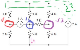
Without being spoon fed that much, can anybody just help me how do I even determine the starting V1 node in order to start solving this with nodal analysis?
>>
>>1064063
If in doubt / no tricks to be seen, write out all the equations and solve the system.
>>
Sup /ohm/
I've always used EveryCircuit for Android to simulate anything I needed, and I'd like to graduate to something for desktop (I use Windows)
I'm a fan of EC's easiness to use and versatility, and I'd like something as simple as possible (I don't use ICs much)
Not asking for a spoonfeed, I'd simply like to hear what you think and what you'd suggest
>>
>>1064063
You have 5 nodes. 3 of them are labelled, designate the green one at the top V4, designate the unmarked one at the bottom ground.
Write out the KCL equations for any four of the nodes and solve.
>>
>>1064087
Falstad circuitjs
>>
>>1064087
LTSpice is great if you don't mind the windows 98 interface.
>>
File: toy tool.jpg (163KB, 2048x2048px) Image search:
[Google]

163KB, 2048x2048px
>>1064087
if you want a real tool instead of toy tools, then you get Multisim.
10 Circuit Design Simulation Apps for Pros & DIYers: http://www.eetimes.com/document.asp?doc_id=1326778
>>
>>1064087
falstad is good if you aren't doing logic
i preferred it to multisim when I was in EE
http://www.falstad.com/circuit/
>>
>>
File: image.png (231KB, 2306x1680px)

231KB, 2306x1680px
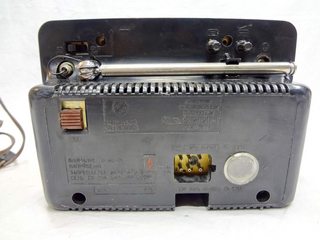
would some anon be kind and read this schematic for me? its a schematic for Shiljalis 402D-1E black and white portable tv which can work on 110, 220 or 12 volts DC
it has 6 pins for plugging in the power and i need to know where do i plug in 12VDC
i marked with red rectangle the place where you should look, its clearly power input because there are 6 pins numbered 1 to 6, like on the device itself
>>
File: s-l1600.jpg (239KB, 1600x1200px) Image search:
[Google]
239KB, 1600x1200px
>>1064291
and here is the connector with pins 1-6 on the back of it
>>
>>1064291
pin 4 is positive, pin 1 is ground, or negative. pin 2 is also used for something but i'm not sure what exactly, coz it leads to a mystery component called I-B2 which is non-standard. could be a relay or switch. we might get a clue if we could see where that dashed line from I-B2 leads to, or how it's labeled in commie.
i'd just connect 1 and 4 and see if that works.
also, i cant say for sure it it's 12V you're supposed to plug in. could be up to 16 based on C3 being rated for 25V.
>>
>>
File: AC-DC adaptor ''International MW88''.jpg (3MB, 4288x3216px)

3MB, 4288x3216px
I have this power adaptor that gets 110V/220V AC and delivers 3V, 4.5V, 6V, 7.5V, 9V or 12V DC. But it has a problem: the 4.5V (only I tested) oscillates so much it reaches 10V. I believe this would fuck completely the devices I could connect to it, so I didn't connected.
I opened, and saw this inside. What is wrong?
BTW, it smells good.
>>
Anyone know if full wave or even half wave rectified current suffers from the skin effect the same way AC does?
>>
>>1064518
It does, kind of. Full wave rectified gives you mostly DC, with some AC superimposed at 2x the supply frequency and higher that makes up the ripple.
At 50/60Hz, unless you're going for super high currents, you don't really have to care.
>>
>>1064518
Rectified AC consists of a DC component plus harmonics of the mains frequency. Skin effect affects the harmonics.
>>
I'm looking to make a pretty simple circuit in theory, but it is turning out to be a bit too expensive using the industry parts I'm used to using for work
I want to have a k type thermocouple, have a few temperature ranges, that it can be "set" to, when it goes below a certain threshold I want a fan to turn on for a certain time, and if the temperature goes too high the fan to go in reverse for a different time
normally I would just hook up a plc and be done, but I am going full hobo mode for this
What I am thinking is taking a thermocouple to DC converter, which puts the output between 0-5V linearly the entire distance
I then take a relay that has about a 5V actuation voltage, then measure the exact voltage that triggers it
I then use a multiposition switch that sends the output voltage through an array of different voltage dividers that would allow that relay to actuate only when the temperature hits a specific range, the only issue is that would allow it to turn on when it reaches a certain temperature, but not turn it back off once it leaves that range
I'm positive I'm overthinking this, I may be able to do this with a cheapo arduino or something but it would be my first time with an arduino
basically I want to be able to make something like this:
https://www.amazon.com/IQ110-Temperature-Regulator-Standard-Adapter/dp/B00A7F1B60
only issue is I dont want to use a low flow fan, I want something a bit beefier with ranges I actually want
>>
>>1064543
BTW reason I am doing this hobo mode is because I'm doing it for personal use not for work
>>
>>1064543
> I then take a relay that has about a 5V actuation voltage, then measure the exact voltage that triggers it
There's a fairly substantial difference between the voltage required to close an open relay and the voltage required to hold a relay closed (i.e. hysteresis).
So in practice, if you're between the holding voltage and the closing voltage, the time taken for the relay to close is a function of vibration.
Also, relays are operated by current. This depends upon the applied voltage, but it also depends upon the coil resistance which depends upon temperature. Operating parameters may also vary with age.
tl;dr: if you want a comparator, use a comparator.
>>
>>1064547
You just helped me substantially already kind sir
I had no clue such a thing existed
>>
File: Capture.png (11KB, 663x541px)

11KB, 663x541px
>>1064543
>What I am thinking is taking a thermocouple to DC converter, which puts the output between 0-5V linearly the entire distance
That's a very bad way to do it. Use two comparators. I've drawn up a little diagram for you.
>>
File: DC-Motor-Driving-using-H-Bridge-600x400.jpg (23KB, 600x400px)

23KB, 600x400px
>>1064560
The next stage of your circuit would be an H-bridge. You can build one from scratch like pic related or get a chip like the L293D that has it built for you. The logic these take is:
A=0;B=0
Do nothing
A=1;B=0
Spin forwards
A=0;B=1
Spin Backwards
This means the comparator circuit I drew can be hooked straight to the H-bridge and it'll control the fan how you want.
>>
>>1064563
>>1064560
wow, you made me feel like a major idiot, but thank you so much, I think I understand it but I am still new to comparators
so I would likely need a few of the comparator circuits each separated with a multiposition switch, but I likely could use the exact same H-bridge
I would still need to use the thermocouple to DC convertor correct?
>>
derp_commander (ID: !!SSXdvR3LCoa)
2016-10-03 04:19:28
Post No.1064571
[Report] Image search: [Google]
[Report] Image search: [Google]
File: schematic.png (10KB, 442x235px) Image search:
[Google]
10KB, 442x235px
>>1064099
>>1064139
>>1064104
>>1064139
Falstad's simulator is basically the thing that got me into electronics in the first place. I probably wouldn't even be in the field without it. Funny thing is though, I initially found the site because I was looking for something to help visualize quantum mechanics for HS chemistry class.
</blog>
>>
File: Clipboard01.png (2KB, 349x362px) Image search:
[Google]

2KB, 349x362px
>>1064563
Better H-bridge for high current. Saturates both sides, avoids the need for separate flyback diodes.
Both of these circuits require that the off/on control voltages are close to the rails (although the previous one requires the "on" control voltage to be above the +ve rail to saturate the high-side switch; better to use a PNP/pMOS instead).
>>
File: Capture2.png (10KB, 551x606px)

10KB, 551x606px
>>1064567
>so I would likely need a few of the comparator circuits each separated with a multiposition switch
If you want to make the temperature points controllable you could use potentiometers to set the reference voltages. In this diagram the potentiometers are connected to resistors to let you set the max and min voltages produced by them. The resistors need to selected such that V1 is always greater than V2 or the logic of the circuit breaks down.
> I would still need to use the thermocouple to DC convertor correct?
Thermocouples already output DC. It's not a linear response to temperature, but who cares.
>>
File: Untitled.png (9KB, 512x512px) Image search:
[Google]
9KB, 512x512px
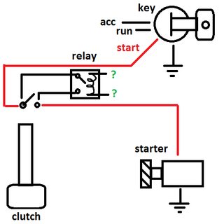
i need a way to power the relay in the pic so that its only closed when the start circuit is engaged to close the clutch momentary switch and opens when the starter circuit is opened. problem is the starter circuit is only able to be opened when the clutch switch is closed so i cant use that to trigger the relay because that would be too easy. just shorting the momentary switch causes a check engine light after a little bit so thats what im currently trying to get around.
how i do dis?
>>
>>1064580
>starter circuit is only able to be opened
starter circuit is only able to be CLOSED
>>
>>1064574
>Saturates both sides, avoids the need for separate flyback diodes.
Only if the intrinsic body diode is both fast and beefy enough, which they usually aren't. If you want to ditch the freewheel diodes, you need to use synchronous rectification, which requires separate control lines to each transistor.
Additionally, for "high current", you would want to use n-channel high-side FETs with charge pumps, since they have superior current-handling capabilities.
>>
>>1064579
Ok, that makes sense to me. I'll likely still use a DC converter solely so I can get finer response but you have done more leg work than I expected in any circumstance
>>
derp_commander (ID: !!SSXdvR3LCoa)
2016-10-03 05:24:49
Post No.1064592
[Report] Image search: [Google]
[Report] Image search: [Google]
File: 1452999135951.jpg (26KB, 479x358px)

26KB, 479x358px
>>1064580
I might be able to help you if you would throw in a few commas so I can understand what you're asking for.
>>
>>1064592
How do I power the pictured relay so it is only closed when the key is in the start position (when starting the car) but is open in any other position? I cannot tap the start circuit because it is only able to be energized once the momentary switch is pressed, which is what I am trying to use the relay for, to temporarily bypass the switch during the starting procedure. I would just short the switch but it causes a check engine light.
>>
>>1064377
thanks, but i forgot to mention, the connector i got with it (with a cut cable) uses pins 1 and 2 (two on the upper left and lower left of socket in >>1064292
)
should i try hooking up 12VDC to these two? im sick right now so i cant take it apart and post more pics, but heres the pic of the part of schematic to which the dashed line goes (i marked it with small red circle)
>>
>>1064609
ok, so it looks like the mystery component is related to the volume control. so i'm guessing when you turn the volume to zero, it switches off the radio. so, that means that if you apply +12V to pin 2, you can switch it on/off, but if you apply +12V to pin4, the radio will always be on. i guess pin 4 is designed to be an output, like they have in car radios, so when you switch it on, it sends 12V out to a motor to extend the antenna.
anyway, using 1=negative, 2=positive seems correct.
>>
>>1064627
thanks, ill try it later today
>>
>>1064582
> you need to use synchronous rectification, which requires separate control lines to each transistor.
No it doesn't. It just requires that you can drive both low-side (or both high-side switches) simultaneously. Which is the case for >>1064574
> Additionally, for "high current", you would want to use n-channel high-side FETs with charge pumps, since they have superior current-handling capabilities.
It depends *how* high. Ultimately, you can use p-channel at any current, but there's a point beyond which it will be cheaper to use n-channel and a proper high-side driver. But that's a non-issue in any context where >>1064563 would be a credible option.
For "equivalent" parts, the n-channel part will have better specs. You can usually find a p-channel part with equivalent specs, but it's going to be more expensive (and possibly have more gate capacitance, which is an issue for high-frequency PWM; that that's not relevant here).
>>
>>1064574
One caveat about this topology: Don't use it if the supply voltage is much more than double the FETs threshold voltage (Vgs[th]), as it's susceptible to cut-through (where both the high and low side FETs are on briefly during the change-over).
This isn't an issue with a 5V supply even with good logic-level FETs, and unlikely to be an issue with a 12V supply and "5V" FETs (below ~8V, they'll still have enough resistance that the cut-through isn't an issue unless you're trying to do fast PWM with a weak gate drive).
>>
File: 20161001_170707.jpg (2MB, 3264x2448px)

2MB, 3264x2448px
>TFW noone cares about your tube project.
input versus output at clean volumes.
obviously the output is inverted and out of phase, I don't think my old scope has a 'flip' function.
>>
Short question, is there anything to know about adding a relay or two on a PCB? I'm fairly new to PCB design and related stuff, so I don't want to fuck it up too much.
Any specifics on how to choose which relay to use?
>>
>>1064658
basically, what you need to know is
- size of the holes required for the pins
- the physical layout of the pins
- the expected load current to make sure your traces are wide enough
- the expected output voltage to make sure you have enough clearance between traces
as for choosing the relay, you use the same criteria as anything else: what current ratings do i need, what size do i need, what am i willing to pay.
some PCB packages will link directly to places like Digikey so you can choose the part and get the layout immediately.
>>
File: Non-working power supply - suspicious capacitor.jpg (3MB, 4288x3216px)

3MB, 4288x3216px
>Switched-mode power supply
>However, unless very carefully designed and using suitable components, switching adapters are more likely to fail than the older type, due in part to complex circuitry and the use of semiconductors.
>Unless designed well, these adapters may be easily damaged by overloads, even transient ones, which can come from lightning, brief mains overvoltage (sometimes caused by an incandescent light on the same power circuit failing), component degradation, etc.
>A very common mode of failure is due to the use of electrolytic capacitors whose equivalent series resistance (ESR) increases with age; switching regulators are very sensitive to high ESR (the older linear circuit also used electrolytic capacitors, but the effect of degradation is much less dramatic).
>Well-designed circuits pay attention to the ESR, ripple current rating, pulse operation, and temperature rating of capacitors.
https://en.wikipedia.org/wiki/AC_adapter#Modes_of_operation
How can I know the circuit was well-designed, before buying?
>>
>>1064704
you cant really, unless you buy from a very small subset of companies with strict quality control, like Apple or IBM. you generally hear about absolute lemons from people complaining about them on the web, but not many people will bother doing that for a cheap item.
>>
>>1064658
Check the spark gap podcast, episode 30. They discuss relays and the different kinds available. All in the context of switching something on and off.
There are many options in relays, and you have to decide whether you go with SMD or mechanical relays. You probably don't want to go with a mechanical option as mechanical things wear down over time faster than solid state components, of course.
>>
File: 20161003_204010.jpg (2MB, 3264x2448px)

2MB, 3264x2448px
>>1064656
put on a simple tilt control.
think big muff tone knob.(no mid scoop though)
helped a bit with how easy it is to drive it too hard and get mototboating.
i think that's it for thes preamp and its time to start on the blues preamp next session.
>>
>>1064775
what are you building anon
>>
>>
>>1064789
Oh thats cool, good luck on your project.
I'm going to casually lurk this place and maybe I'll learn enough to make a guitar pedal at some point.
>>
>>1064510
Looks like someone dropped a bit of 5.5V hot chocolate on it.
>>
>>1064855
pedals are pretty easy mang, and discussed here frequently.
i got an electronics background, but im willing to bet most most pedalbuilders are guitarists who went one step further in their quest for 'toanz'
spring for a kit and follow the instructions to the letter if you don't wanna go down the electronics rabbit hole. most shops have good instructions
come here and post resoults, good or bad.
>>
Anyone got any ideas on how to use resistors, diodes, and zeners to limit power to an LED over a range from 2-24V while still having it be lit on the low end? Forward voltage drop approximately 2V, current limit is 30mA. I've been racking my brain trying to think of a way to do it for around 2 hours.
>>
>>1064878
>5.5V hot chocolate on it
What is this?
>>
>>1064888
I want to buy some parts on my own then build a clone.
I'll do that after learning a bit and getting good schematics/instructions.
I'll be sure to post here when I do.
>>
File: Clipboard01.png (2KB, 272x354px) Image search:
[Google]

2KB, 272x354px
>>1064914
Can't be done. You need to increase the minimum voltage above the LED's own minimum voltage, at which point you can do it with two resistors and a zener (pic related).
Note that if you set a minimum voltage which is only barely above that of the LED, R1 needs to be quite low, in which case, you're going to draw quite a lot of current at maximum voltage.
You can do better if you're willing to use a transistor.
>>
>>1064964
Thanks. That makes me feel much less stupid.
>>
Quick question, can an optocoupler get damaged from a capacitor dripping electrolyte on it?
>>
>>1065032
Electrolyte is conductive. This is a problem in itself and the resulting leakage current can also damage the opto. Other than that... Unless the opto looks clearly damaged (corroded), it shouldn't have any effect.
>>
>>1065042
The spillage doesn't seem to have reached the contacts of the optocoupler, so I should be okay just replacing the cap, thanks.
>>
I'm still using a crappy Radioshack soldering iron, and need to upgrade to a proper soldering station. I'm thinking about grabbing https://www.amazon.com/dp/B01DGZFSNE/ now, and then springing for something like a Weller WD1001 in the future, if I find I need something nicer/easier to be more precise with. Thoughts?
>>
>>1065073
why not skip the side trip into the land of exotic no-reputation brands, and go directly to Wellerland. A WP30 is cheaper and you know you've good a quality iron that'll lost longer than your marriage. Plus the tips may be (maybe) used in other Weller models if you upgrade.
>>
>>1065042
>Electrolyte is conductive.
No it's not.
>>
>>1065085
a good sellingpoint of major brands is that you know new tips will be available for a long time.
>>
Daily reminder tubes offer no audio quality over transistors and if you use tubes you're just latching onto dead technology.
>>
>>1065151
okay.
>>
>>1065151
>latching onto dead technology.
and?
is there something wrong with that?
should I throw out all my to-92 package transistors and dips?
should I toss all my VFDs, nixies and incandescent displays because LED and LCD is 'current'?
are you that guy who went apeshit when some anon used a darlington instead of a FET?
you might not agree, but I'm quite convinced there is something to behold in tubes when applied to guitar amplification.
overdrive characteristics are quite cool.
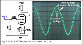
I think the island effect is a big part of this, cut-off clipping is not sudden but instead
leaves a rounded edge on the waveform
inherent nonlinearities also contribute.
remember, these are not HIFI amplifiers, they are made to shape and distort sound.
now, I'm sure its possible to make these same characteristics with solid state devices if engineered properly.
hell, even DSP's.
but is there any reason NOT to use tubes?
guitarists eat it up, and I like making shit that others like to use.
I make pedals too, is that cool just because its solidstate?
russian NOS stocks are cheap, the only real costs are the transformers.
why is the 6axis sex robot ok, but tubes are a waste of time?
>>
File: Screenshot 2016-10-04 20.48.44.png (83KB, 365x198px) Image search:
[Google]
83KB, 365x198px
>>1065254
>>
>>1065109
Could it be that you're assuming it to be there to act as an insulator? That's aluminum oxide's job. The electrolyte is there to form the other "plate" of the capacitor.
>>
Can anyone recommend any decent rechargeable batteries that could support around 4 to 8 5v/6v RC servos/motors?
This is for a robot that would be running on a table, so no particular weight constraints other than "not the size of a car battery."
>>
>>1065254
>replying to bait
>>
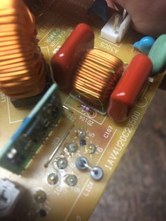
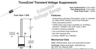
anyone got a clue on identifying this zener diode? its on a power supply to a sanyo plv-1080hd projector.. is showing 0 resistance both ways, so is blown and needs replacement.
>>
File: IMG_9130.jpg (1MB, 2448x3264px) Image search:
[Google]
1MB, 2448x3264px
>>1065309
forgot pic
>>
Cox*µn*W/(2*L)(Vgs-Vth)^2(1+λ(Vds-Vds-sat))
>>
>>1065311
solder it out before you test it.
might be something in parallel, not the zener itself, like that coil.
>>
File: transzorb.gif (107KB, 1576x811px) Image search:
[Google]
107KB, 1576x811px
>>1065311
it would be weird to see a zener in a situation like that, so it might be a TRANSZORB which is sometimes drawn like a zener, or as a diode.
>>
>>1065151
there's more to it than that. the harmonic content of a traditional vacuum tube amp when it's distorting is measurably different than a "solid-state" amp doing the same. many people prefer the sound of a distorting tube amp over an equivalent amp that uses exclusively "modern" technology. it is possible to emulate the behavior of a distorting vacuum tube, but it's often easier for a hobbyist to simply use the real thing.
that being said, in situations when distortion is not desirable (a home stereo, for example), vacuum tube amplifiers cannot keep up with solid-state amplifiers in terms of performance.
>>
>>1065493
> it is possible to emulate the behavior of a distorting vacuum tube, but it's often easier for a hobbyist to simply use the real thing.
Whereas emulation is much easier for a commercial product. Valve-based designs often need multiple power rails, generate heat, are physically fragile, and may require higher voltages (pushing up the cost of UL/CE testing significantly). Critical parts may be single-source from small-scale suppliers. Product variation may require units to be individually "tuned", or may even result in variation in the final product.
>>
File: Fan that can spin its blades only for a short time.jpg (3MB, 3216x4288px) Image search:
[Google]

3MB, 3216x4288px
I have here this fan. When I plug it on the socket, it can spin its blades, but short time after, it cannot anymore. So, the engine itself probably isn't completely lost.
Is it worth to fix?
>>
Hey ohm, I want a bit of advice.
I'm making a relatively simple bench power supply
>picture related
I decided to forgo the R2 of the LM317 and use a voltage divider on an op amp to select the voltage for more linear performance.
Problem is the second op amp will have to drive ~30V into the adjust pin of the LM317.
My problem is I can't also get zero volts output if I want to have 30V max output (op amp limitation)
Any suggestions on how to get around op amp limitation? 40V+ supply rail op amps aren't easy to find.
So..
I want zero volts.
>adjust pin has to be driven negative
>adjust pin has to see as low as -1.5 or -2V
>negative supply needs to be at least 3V lower
>-4.5 or -5V
>max output of 30V
>positive supply needs to be at least 3V higher
>33V
>33 - (-4.5) = 37.5V
>most op amps take a Vcc - Vee = 36V
Also any pointers on shit i'm doing really bad is helpful
>>
>>1065614
Forgot to mention it'd be supplied by a boost module, changing an old computer PSU's 12V to ~35V
>>
>>1065614
IC3 is supposed to be two op amps in one 8 pin package. op amp A is just a 2.5V on the input with a gain of 2 to get 5V output put across a pot to ground. the wiper is determines the voltage output.
The wiper of the pot goes to the input pin 5 of op amp B, which compares that voltage to the output voltage (max of 30v here) by putting it through a voltage divider (divided by 6, so that the op amp sees 0 - 5V, just like the voltage select).
op amp B then outputs voltage into adjust pin of the LM317 until the the divided output voltage going to pin 6 matches the reference voltage on pin 5. I feel like there should be a better way to do this than by simply getting a higher voltage op amp.
pass transistors provide increased current, pot on the output of the LM317 is basically a current limiter
>>
>>
>>1065621
>and will work perfectly fine at 50V without a care in the world. i've see a perfectly happy 741s working at 60V.
>60V
not buying it
>>
>>1065623
thats coz you're used to digital chips that get hot if you go a quarter volt too high. the analog world isn't like that.
>>
>>1065626
Cool. prove it.
all the datasheets say +/- 18V
>>
>>1065626
absolute ratings are +/- 18v or +/-22v for 741M
a far cry from 60v.
>>
>>1065628
the datasheet is what the manufacturer guarantees will work. real life testing and experience tells you how far above the guaranteed ratings you can safely go. a chair rated for 200 pounds is not gonna collapse if you weigh 201, or even 250.
>>
>>1065632
because electronics 'absolute maximum' ratings are just fucking around right
>>
>>1065634
no, you dense motherfucker. it depends on the part. some you can overdrive by a lot, some by a little. i repaired boards for a phone company, where the power supply was 60V, and routinely saw op-amps working at 60V when the protection zeners died. not once did i have to replace an op-amp because of it.
a number on a page does not overrule reality.
>>
>>1065632
However, you can't empirically test the absolute maximum value for any given component without destroying it in the process.
>>
>>1065638
right, but if you're not trying to determine the max rating, but just wanna know if it's reliable at a desired rating, it's a lot simpler: you just wire 20 samples and run them for a month.
>>
>>1065640
That won't reliably tell you which ones will last another month.
Quality control involves first understanding the failure mechanisms, then finding properties which a) strongly correlate with failure and b) can be measured non-destructively.
>>
>>1065637
That's poor practice. I hope nobody here takes your advice.
>>
>>1065614
>>1065615
>>1065619
Might've figured out a solution that works. Instead of connecting the output of IC3B directly to the adjust pin of the LM317, I connect the adjust pin to the collector of a PNP transistor, and the emitter to ground. I connect the output of IC3B to the base of the transistor. Seems to work, though its not quite accurate the way directly connecting the output to the adjust pin seemed to be
>>
File: Flat-Flex-Cable.jpg (56KB, 1024x669px)

56KB, 1024x669px
I'd like to break out the connections from a flexible flat cable (pic related) to, let's say, a breadboard. I was thinking of etching something like an edge connector and clamping the cable down to it with something.
Is that a good idea? Any suggestions?
>>
>>1065567
>Whereas emulation is much easier for a commercial product.
Depends on volume. Small-time shops that build ~100 units a year might not care about that stuff. Those negative things might be considered "good" due to some "mojo" factor or whatever is hip at the time. One may consider this to be stupid, but if it helps sell units then who cares?
Anyway the point is that a blanket statement of "valves are bad and you should feel bad" is pretty ignorant of the different capabilities and needs of the wide number of individuals or groups that create electronics.
>>
>>1065637
a DC power supply is dangerous enough that running a component in it beyond it's rated value is a really bad idea. there are indeed situations where you can run something beyond datasheet specs, but doing that in something that can burn down your house is really fucking dumb.
don't forget that a given part number may come from different fabrication plants, may be built on different days (or years!), may be built with different processes, etc. all these things may affect the part's performance past it's rated values. how could you tell? is it worth the effort to test all these cases empirically? wouldn't it be better to design away the problem?
>>
>>1065671
can you draw up a new schematic? hard to tell exactly what you mean without it.
here's a shot at your question though:
closing the opamp's feedback loop around the BJT should eliminate VBE error, but you will still have base current error. with a higher-gain BJT, this base current error will be reduced. you could try a darlington if you can find a normal PNP with high enough gain.
>>
>>1065738
*if you can't find a normal PNP
>>
>>1065632
What those ratings mean isn't when a specific part will fail, but when on average most of the parts drastically drop their life expectancy. So yeah, if you exceed them it might work. For a while.
>>
>>1065726
glue it down to a protoboard and just solder connections to it to a header?
keep in mind that a single row of headers for all these would be over 3 inches long^^
>>
>>1065734
>different days (or years
its an lm741
we are talking decades and decades :D
>>
File: rps20160927_165907.jpg (109KB, 900x1200px)

109KB, 900x1200px
My friend had ripped out the power cable on this Behringer Xenyx 1202fx mixer and some of it got stuck in this piece. The power supply for it is PSU6-UL.
How do I find the name of this part so I can replace it and where can I order one?
>>
>>1065810
Looks like a 3 pin din socket
>>
>>1065739
>>1065738
like that
>>
>>
>>1065823
>3 pin din socket
Yes! Thank you this was exactly what I was looking for
>>
File: image.png (32KB, 2997x946px)
32KB, 2997x946px
>>1065897
looking at your schematic, it's not really relevant for your application anyway.
can you describe or show the error you're seeing with your configuration? my gut feeling is that IC3B is reacting too quickly to the difference in programmed voltage and output voltage and the feedback loop can't stabilize.
>>
>>1065909
the left part of the picture should say "vload = vin - vbe"
my bad
>>
>>1065909
At less than one volt, there's high frequency output on IC3B. It can be mostly eliminated by putting a capacitor to ground on the base of the transistor (in the second schematic). If i zoom right in there's still really really tiny sub milivolt noise.
But to answer your question, isn't IC3B closed in that way?
>>
>>1065919
so is the output working at all? is it just noisy? about what frequency is the noise? a capacitor to ground will help of course, but you should also put one on the controlling signal from R7.
>>
What can I use an oscilloscope for?
I know what they do and how to use one but I can't think of anything that I could do/make to take advantage of it.
>>
>>1065935
For educational purposes, you can build different wave generators and see your result.
For debugging and reverse-engineering circuits, they have endless uses. Think of what you can use a voltmeter for, then think of when it would be helpful to be able to graph what's happening to the voltage when it's changing quickly, to zoom in on recurring patterns.
>>
>>1065925
That's a good idea. Should probably put a small value cap across ground on the wiper. Where would the cap discharge to when the power's turned off?
the noise when low voltage is about 10kHz, and less than 50mV p-p.
granted i don't have the exact circuit put together. I'm using a resistor voltage divider instead of a precision voltage reference through an op amp with gain = 2, for example. I'm using LM741s instead of the TL082 that i intend to use
>>
>>1065968
the cap from R7's to ground will discharge through R7.
50mV at 10kHz isn't the end of the world for a circuit like this. Using a real voltage reference instead of a divider will help you there. Better opamps and voltage regulators will help, too. You could also safely increase the capacitance on the output rail. Remove R3, it's just adding johnson noise; to this point you could also reduce the values of R4 and R5. Add a capacitor from the output of the LM317 to ground, 100nF or so. See how it goes then.
>>
>>1065986
Yeah I wasn't sure about adding R3 initially, since op amps are high impedance inputs anyway.
That's a good point about R4 and R5. I just kept thinking of trying to reduce current draw lol.
And about the output cap for the LM317, it's sorta there, it's just on the base of the 2N3055s instead of right at the output.
thanks for the pointers
>>
>>1065988
the output cap for LM317 should be connected directly to it's output pin and physically close to the chip.
good luck with the circuit, it seems like you're on the right track with balancing noise requirements with quiescent current draw. keep going man!
>>
>>1065999
Gotcha, I'll do that. Probably put a 1 uF on there. the datasheets of the LM317 don't specify having a small value cap near the chip on the output though - only the input.
Thanks! I can't take credit though. I got the schematic off a different site. something along the lines of 0 - 28V 6-8A power supply. I understand how the LM317 drives the pass transistors now. I opted not to go for their dropping to 0V via diode method.
Basically the only things i adjusted were wanting linear voltage adjustment heaviour. Having a pot in the usual connection with the LM317 doesn't produce linear pot behaviour. And the other thing was wanting zero volts output.
So now i'll build it up on a breadboard, and check how the output is with no load, and across the range of voltage selections and current limiting. Then again but under load.
Thanks dude!
>>
>>1066009
>>1065999
So since i have pots to test this with now, i notice the LM317's output voltage is negative at the low end of the voltage select. It jumps from 0 to about 0.3V, and its at this time that the output voltage (from emitter of the pass transistor) starts increasing. Is this just the transistor coming into the on state? or is it to do with imperfectly matched inputs on IC3B
>>
EE student here with a question for EEs: what do you even do when you get a job? I mean, the stuff they teach at school seems pretty non-specific. What's the transition like from school to the field?
>>
File: PCB-GL0009.jpg (118KB, 1000x750px) Image search:
[Google]

118KB, 1000x750px
>>1065726
Etching a breakout board for a ffc is a massive pain, just get one of these
>>
I'm having a bunch of 2.1mm/5.5mm 5V power supplies that I plan to use with a PCB I'm currently designing. But for the life of me, I can't find a jack that I can put on the PCB in Eagle and buy in bulk from ebay.
I mean, it can't be that hard, right? Is there some kind of standard that I'm missing?
>>
>>1066182
I have limited experience with eagle. You could just manually put voltage sources in the schematic, and pads in the board layout? not ideal I know.
Alternatively you can just pick any appropriate connector (same no of pcb connections) and place that on the board. When you go and make it you simply solder wires instead of the jack, then you solder the wires to the jack?
>>
File: Bent transformer.jpg (3MB, 4288x3216px)

3MB, 4288x3216px
This transformer has its iron part bent. Is it still usable?
>>
>>1066220
test for continuity and shorts in the coils.
then clap it back in shape and don't worry about it.
>>
I want to build some projects off of power tool batteries. I specifically want to use my power tool batteries, rather than better alternatives. How do I go about figuring out what a safe amount to draw from the battery is?
>>
>>1066234
read the datasheet for the drill/powetool?
should have peak and continuous current ratings.
they are probably really high.
what do you want to power?
>>
>>1066235
I'm not able to find datasheets for powertool batteries, at least my Milwaukees.
>>
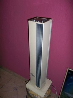
File: Tower fan that cannot spin its cooling cilinder.jpg (3MB, 3216x4288px) Image search:
[Google]
3MB, 3216x4288px
I have here this tower fan whose spinning cylinder does not spins anymore. Is it worth to fix?
>>
>>1066245
Yes.
>>
>>1066050
the output of the LM317 can only go negative if the voltage at the adjust pin is more negative. all the LM317 knows how to do is attempt to make its output voltage 1.25V higher than the voltage at its adjust pin.
for 0V output of your circuit, the output voltage of the LM317 would have to be about 0.7V, meaning the voltage at the adjust pin would need to be about -0.55V. what are IC3B and Q1 doing in this case?
>>
>>1066078
i can only speak for myself of course, but most of my day is spent designing circuits and then laying out the PCB. so that includes quick hand calculations, SPICE simulations, component selection, then the layout of course. if i'm not sure something will work, i will jerry-rig shit together on a breadboard or something to test it out. the best part of my day is sneaking in cool artwork onto PCBs where no one will notice until we've already paid for hundreds.
>>
File: 18ixbt37xuqsojpg[1].jpg (36KB, 636x358px) Image search:
[Google]
![18ixbt37xuqsojpg[1] 18ixbt37xuqsojpg[1].jpg](https://cdn.4archive.org/diy/thumb/1475/773/1475773367314s.jpg)
36KB, 636x358px
>>1066244
If you crack the case open you will find cells inside that you can probably find datasheets for.
>>
>>1063427
If you're going to school for EE, the school is going to give you access to way more stuff than you could afford. I'd just roll with that for now.
Look into student groups too. When I was in school they had one for a solar car, one for a battle bot, etc etc. The student groups get funding to buy parts and they get after hours access to all that sweet university lab equipment.
>>
It feels like a shame that I keep buying new cans of compressed air to clean out old electronics. There's just something about it that feels necessary but slightly wasteful.
Are there any recommendations for an alternative that doesn't require me to keep buying new cans?
>>
>>1066429
a tiny air compressor?
>>
>>1066442
Are those reusable? You honestly have to treat me like a moron on this because I have no idea.
>>
I want to get into micro-controllers, but there is one small problem
I love signal processing and micros don't have enough RAM.
What do you recommend I do?
Buy a dedicated signal processor from TI or Analog Devices?
any experiences?
>>
File: garbage.jpg (69KB, 600x402px) Image search:
[Google]
69KB, 600x402px
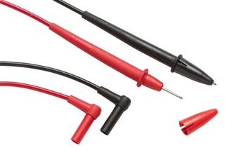
Just got a Fluke 15b+, and while the unit itself is super nice the leads are pretty damn disappointing. Cable is OK i guess, but the actual handles and tip feels dirt cheap and not comfy at all. I mean the super cheap mastech ones from my old meter feels tons more solid and better to hold.
Is this just a dirty scheme by fluke for selling their more expensive premium leads? And are those worth it by any chance?
>>
>>1066479
I guess I have those Fluke's "premium leads", newer and older pair.
The tip shape is the same in both and at least superficially the same as in your pic. The newer ones have short threaded sections, allowing attachments like crocodile clips. The newer ones also have built-in tip shrouds.
The basic handle shape is very similar to your pic, except the molding has stiffer plastic near the tip and rubbery material over the rest of the handle.
I'm not a fan of the tip shroud thing in the newer ones and the screw-on attachments like to loosen themselves over the time. Getting a good contact often requires uncomfortable amount of pressure, too. No complaints about the handles, though.
>>
>>1066479
>Fluke 15b+
This fluke is made in China
you just got chink'd
>>
>>1066447
Add some external RAM and/or use bigger controllers.
DSPs aren't really about huge on-chip memories.
>>
File: Faxfilters.jpg (3MB, 4288x3216px) Image search:
[Google]
3MB, 4288x3216px
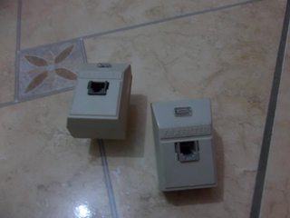
I have these faxfilters that were used from 2004 to 2008 when I had dial up connection on my home. I don't know why these were bought in the first place, as there are no faxes machines on my home. They are not working as ADSL filters. Should I fix/change them so it can work as an ADSL filter? Is it worth?
>>
>>1065935
Not really related but I thought I'd share the most ghetto experience in the history of electronics, which is the oscilloscope I used before graduating tithe one I have now
It was a small 8Ohm speaker connected to a small op-amp circuit that took input from the probes, and the sound was then received by my smartphone's mic and drawn with an oscilloscope app
Pretty useless for voltages and the like but works for anything like PWM
>>
>>1066523
>Is it worth?
they sell ADSL filters at the thrift store in bags of five for a dollar. so, no.
>>
>>1066276
Don't quite remember the setup when i wrote that. It can do zero volts though.. at least without the transistor...
Later it was able to get zero volts with a transistor there, but now with the same setup, it only goes as low as 0.77V. kinda puzzled
>>1065890
more or less set up like that at the moment. but with 12V as input, set for 10V output max, with 2.2k x2 voltage divider to divide by 1/2 instead of 1/6 (since i'm not dealing with 30V), and only using one transistor since i seemed to have burned the other one out, oops.
Except now it doesn't seem to pull the base of the transistor low enough to get zero volts output at the emitter of the transistor (output of the circuit)
Yesterday when I was getting zero volts with that same setup. not sure what i missed or changed.
also I notid that the IC3 was getting a little lukewarm at times
>>
>>1066282
Wouldn't you get a reprimand for that lol
>>
>>1066444
Not the guy you're responding to, but an air compressor is a powered device that compresses air as its name implies. You access compressed air with a compressed air line and whatever accessory you want hooked up to it. I'm sure you've seen in shows or videos in shops where people have this coiled yellow tubing. that's a compressed air line
>>
>>1066570
>>1066276
Okay this seems familiar now. With the 100 ohm resistor (R15) connecting the collector to ground (far right, Q1), it'll let it get pulled low enough to get zero volts at the output (top right)
Why is that though? With it configured like that, the base of Q1 actually gets to -2.28V. the adjust pin of the LM317 gets pulled to -1.44V as is the collector of Q1.
Why wouldn't it do that in the absence of R15?
>>
>>1066447
> I love signal processing and micros don't have enough RAM.
What kind of signal processing are you envisaging that needs a lot of RAM?
>>
>>1066213
Thanks, but at that point I probably just order some random fitting ones from ebay and design the part myself for Eagle. That's better than directly placing the pads every time, saves time in the long run.
>>
>>1066724
how do you make parts in eagle?
>>
>>1066774
I only did it once yet and followed an instructable. It's pretty easy, just get the documentation, draw some lines and pads on the specified spots and then do some eagle magic that I can't recall right now.
Just google "eagle make parts", one of the first links is the one I'm talking about.
>>
>>1066776
cool, thanks
>>
File: VID_20161007_174036.webm (3MB, 1280x720px) Image search:
[Google]

3MB, 1280x720px
Who multirotor here?
>>
File: 1474747438803.jpg (15KB, 211x238px)

15KB, 211x238px
So, I need to make an induction furnace to melt some raw materials. I was wondering if it would be practical to run 60Hz AC grid power directly through the induction coils without the need for a high frequency power supply. I'm melting basalt, which is moderately conductive, but I don't want the heating to be concentrated at the surface from high frequency skin effect. What do you guys think about this?
>>
>>1066888
60Hz is a pretty low frequency for skin effect to happen, but I have no idea
>>
>>1066956
Skin depth is around 10mm with normal metals at 60Hz. It increases as the conductivity decreases, but I have difficulties believing that room temperature basalt is conductive enough to be heated with a 60Hz induction heater.
50/60Hz induction heaters exist.
>>
>>1066964
> 50/60Hz induction heaters exist.
They tend to be fairly large. Most induction furnaces use higher frequencies in spite of the cost of the inverter.
At 60Hz, you'll need a /lot/ of turns to get much inductance with a basalt core.
>>
File: Door Bell - external.jpg (3MB, 4288x3216px)

3MB, 4288x3216px
I have here this old Door Bell. See? Left you see it, right you see the respective paper box. It does not works.
1/2
>>
File: Door Bell - internal.jpg (3MB, 4288x3216px)

3MB, 4288x3216px
>>1067010
Here you can see the internal circuit. Someone cut the tracks at 2 points. I don't know why, but I know that people tend to fuck their equipments when they stop working. So repairing the tracks with solder would not be sufficient, probably it has more problems.
Anyways, is it worth to fix?
2/2
>>
>>1061668
I want to simulate RF integrate circuits, what software do you recommend since the OP software lost doesnt work at high frequencies ?
>>
>>1066888
if you cook stuff and don't want it to burn, then you must place a gllas/ceramic bowl in a bowling pot with water.
this is how they melt chocolate etc
ps: maybe I'm too high to understand your question. Im not gonna read it again/
>>
>>1067012
that's not someone destroying the gadget, that's a reasonably well-done hack, or a mod. probably done by the manufacturer themselves to correct a PCB error. you used to see lots of these flying wires in commercial projects back in the day. if you correct it, it will likely never work.
>>
>>1066966
So the higher frequency the better?
Are there any good ways to calculate inductive heating for various core materials, frequencies, and coil configurations?
>>
>>1067049
Ooops, I did not pay attention to the wires themselves on all these months... Thanks!
So, is it worth to make it functional by replacing the battery support (2x AA), putting new wires to the external button, and later replacing the battery support for some power adaptor?
>>
>>1066594
my last reply was lost, but here's the short version:
wiring up Q1 like you have is probably not good since it puts the circuit in a weird situation on startup. you want to replace Q1 with a common-emitter amp and drive the LM317's adjust pin with that. this will reverse your control logic since the common-emitter is inverting, so you will need to take care of that.
>>
Just curious but would coilguns be acceptable in this thread?
>>
>>1067297
I guess, i mean you are posting in a designated shitting board to begin with.
>>
>>1067297
typical coilguns are no more dangerous than a blunt pencil, so they hardly qualify as weapons.
>>
>>1067294
I am not sure I am following?
And I'm finding that putting a transistor doesn't really get rid of my problem either. the op amp still needs to push ~30V into the adjust pin when i eventually try to drive this thing at 30V. i thought the transistor might fix the issue but it doesn't. Without the transistor and driving adjust pin directly, the op amp saturates to the -12V rail when i get it down to zero volts. not sure why. so basically i'm still more or less where i started. Except with the transistor and resistor on the collector, it doesn't try to bottom out the voltage when i'm trying to get zero volts on the output
>>
>>1067061
> So the higher frequency the better?
Yes, up to the point that skin effect starts to be an issue (it's much more of an issue with materials with very low resistivity, i.e. pure metals). The impedance of an inductor is proportional to frequency, so low frequencies result in low impedance (i.e. you'll need a low-voltage high-current supply).
> Are there any good ways to calculate inductive heating for various core materials, frequencies, and coil configurations?
Faraday's law tells you EMF as a function of rate of change of flux, which depends upon frequency, core permeability and coil configuration. Eddy currents are a function of EMF and core resistivity, power dissipation is EMF times current.
In turn, any changes to the eddy currents induce an opposing EMF in the coil. This is where you get real power consumption in the electrical side (without it, a coil with negligible resistance would be a purely-reactive load and thus consume no power).
The hardest part is probably calculating flux. You can get equations for ideal solenoids etc, but practical inductor calculations tend to use finite element analysis.
>>
>>1067392
Thanks man!
Some napkin math shows that I'm going to need something at least around 1 MHz running at 50 amps for my application. No idea how I'm going to do that on my shoestring sideproject budget though...
[spoiler]I'm an ME so I have no idea what I'm doing[/spoiler]
>>
>>1067407
*50 amps peak current
>>
if i have a power meter that is calibrated for a 100adc 75mv shunt. i want to use this to calculate up to 200adc. im sure if i just slap on a 200adc 75mv shunt it will read wrong or pop right? how can i make this meter read up to 200adc?
>>
>>1067407
>I have no idea what I'm doing
You know, there are plenty of books written about the topic. They're guaranteed to give you better a idea about the effects of the frequency than anon's guesses based on skin depth. Same with the heating effect, no need to start from Faraday's law.
Go to a library or start googling.
>>
>>1067420
You could try a 200A 150mV shunt, but there's a chance your meter won't show anything above 100A.
Or you could use a 200A 75mV shunt, but then the measured current and power would be a half of the expected value. 1000A 75mV shunt would show 1/10 of the correct value, which would be more convenient.
Or, if you're lucky, your meter has jumpers or something for configuring the scale.
>>
>>1067424
might go with the 200/150 shunt if i can find one for not too much money just to give it a shot. if not the 200/75 are easy to find and i could just remember to double the output. i doubt it is programmable or recalibratable seeing as its a $20 amazon meter but ill check.
>>
>>1067380
>>1067294
I had to look up common emitter amp. Anyway this doesn't help me either because the voltage gain is roughly 1, which means i'm gonna have to push 30V into that transistor anyway. was hoping I could just work with +/- 12V
the other issue with driving the adjust pin is that when i set the output for zero volts, the op amp drives the full negative rail (as far as it can go anyway) into the adjust pin. I'd rather not have the LM317 be putting out negative voltages
>>
>>1067424
popped it open and there are no trim pots or anything to adjust it unfortunately.
>>
>>
>>
>>1061668
what gauge of wire would i need to handle 200 amps for a power supply/generator?
>>
>>1067469
dude, you can type that exact question into google and get a definitive answer.
"what gauge of wire would i need to handle 200 amps"
>>
>>1067462
They're output capacitors and the user might put anything in parallel with them, including even more capacitance.
I'd worry more about C6/C7.
>>
File: Texaco Marfak MP2.jpg (3MB, 4288x3216px) Image search:
[Google]

3MB, 4288x3216px
>>1065621
>if you have grease, then it'll be good for several years.
I have this grease.
>TEXACO MARFAK MP2
>Multi-application grease
>expiration date: 2007
Should I use it?
>>
>>1066223
>test for continuity and shorts in the coils
Using my digital multitester?
>>
>>1067539
multimeter... either use continuity beeper or just measure ohms
>>
>>1067543
Couldn't the increase of tension by the coils fuck my multimeter?
>>
>>1067544
If by tension you mean voltage, and if you worry about it, you can put a protection diode across the coil in such a manner that the current flowing through the multimeter into the coils couldn't pass through the diode, but when the multimeter is disconnected, the current flowing through the coils could close a loop through the diode.
>>
>>1067546
I couldn't understand the purpose of the diode in this case. What exactly would it be preventing?
>>
>>1067549
https://en.wikipedia.org/wiki/Flyback_diode
>>
>>1067392
>>1067407
>>1067421
Would there be anything wrong with using some kind of off the shelf RF power supply to generate a 1MHz/ 50A peak/ several kilowatt signal? Would the furnace coil's very large inductance pose an issue for those kind of power supplies?
Are there parts that I could potentially scavenge out of discarded home electronics and/ or appliances to use as a power supply? Or it would it be cheaper and easier to roll my own from scratch?
>>1067421
I'm not quite that far yet. This intended to be an extremely rudimentary proof of concept where cost is a much bigger limiting factor than designing something that's pretty. I just need a way of internally heating this chopped basalt fiber I have.
>>
>>1067553
I'm more worried about normal operation of the coils, than some exception. The normal operation of the coils increase tension, so wouldn't this fuck my multimeter?
>>
>>1067592
I don't understand what are you talking about. If you are talking about voltage please use the term voltage.
The transformer coils do increase AC voltage, but only if there is AC voltage applied to the primary winding. What you should do is to check whether the coils are still:
1) intact, i.e. you can measure relatively small resistance across the primary and secondary winding
2) not shorted, i.e. you can't measure a short between the primary and secondary winding
and you should do these things when there is no power connected anywhere to the transformer. The coils won't amp up any voltage from the multimeter because the voltage the multimeter applies to the coils is DC, not AC; and even if they did, multimeters should survive thousand of volts overloads.
Anyway if you don't know how to measure resistance between two ends of wire and don't know how transformers work in generally you probably shouldn't be using them.
>>
File: Screen Shot 2016-10-08 at 1.47.13 PM.png (429KB, 590x399px) Image search:
[Google]

429KB, 590x399px
What math do I have to do to calculate how long I can run this tv off lithium batteries? I want to be able to run a panel for like 3 hours or so
https://www.vizio.com/e32c1.html
>>
>>1067597
>https://www.vizio.com/e32c1.html
>Power consumption 27.95W
PUlling
>http://www.batteryspace.com/lifepo4battery12v20ah240whwithcontrollerforsolarpowerstorage.aspx?gclid=CK-cpuLjy88CFQuSaQodGKAEwg
as the first google for lithium battery pack
12.8V 20Ah => 256Watt Hours
(256 Watt hours) / (27.95 watts) = 9 hours
>>
>>1067605
many thanks
>>
>>1061668
how can i change a modified sine wave from an inverter into a pure sine wave on a very small scale, just enough to measure the ac output of the inverter with a meter that cannot tolerate modified sine? or can someone recommend a meter that can tolerate modified sine for about $20 or less that shows at least voltage and amperage?
>>
>>1067526
yeah C6 is just fine. C7, if its a 1uF or bigger, introduces ripple. As does a cap on the output of the LM317. I am out of ideas lol
>>
>>1067596
>The coils won't amp up any voltage from the multimeter because the voltage the multimeter applies to the coils is DC, not AC
OOPS, I ignored this fact. Thanks.
>>
>>1067549
It isn't necessary.
>>
>>1067573
> Would there be anything wrong with using some kind of off the shelf RF power supply to generate a 1MHz/ 50A peak/ several kilowatt signal?
Cost. Also, RF amplifiers designed for radio transmission tend to be fairly fussy about the characteristics of the load.
Really, you need to read a book on induction furnaces. I don't know much about them, but a basic knowledge of electronics is enough to know that doing this at 1MHz is going to create problems.
>>
>>1067619
Any multimeter will tolerate modified sine, although it won't necessarily give a true RMS reading.
But passive conversion (i.e. feeding modified sine through a band-pass filter) will have the same issue.
>>
>>1067642
i want to use a volt/amp meter to mount to the inverter so i can see how much power im drawing but every one ive come across says to not use mod sine or it will break it. i figure if i can make it pure sine just for the meter it can give an accurate result without frying or having to convert the whole thing or buy a new one
>>
>>1067428
common-emitter amps can definitely have gain greater than one, which is exactly why i recommended it. i'll draw a picture later.
>>
File: 11 october 2016.jpg (537KB, 870x1219px) Image search:
[Google]

537KB, 870x1219px
>>1067642
>a true RMS reading
A true RMS reading will happen day 11. Just wait some days and you will hear him reading.
>>
>>1067652
The brief stuff I've looked up (lol wikipedia, and the few few articles on google) seem to suggest that the gain is in most situations roughly 1, with any reasonable resistor values. Otherwise yeah it was seeming like a good idea.
>>
>>1063983
gotta tell ya i got one based on your shilling i bought the $25 dso138 kit and its pretty fuckin slick. literally the hardest part was identifying each resistor value because they were so damn small but other than that it only took a few hours and that was actually trying to get everything soldered in nice and pretty.
>>
if im trying to measure the output ripple of a dc-dc buck converter, do i put the scope in ac or dc? because in ac there is a small ripple of about 10mv, but in dc its dead flat.
>>
>>1067846
AC just removes the dc offset of the waveform. It's more convenient to look in AC, since you don't have to scroll up / down to see where the waveform is
>>
>>1067849
>AC just removes the dc offset of the waveform
no sure what that meanss, does it mean instead of starting the wave it its voltage level it does it across 0? either way, when i do it in dc the output is dead flat, no waves or ripples or anything, and i find it hard to believe a $20 chinese buck converter is completely ripple free
>>
>>1067852
It sounds like what you describe, yeah.
Which buck converter are you using? I also have one and its pretty fricken clean, even under high load.
As for your main question though, I'm not sure. I dont' knowo why the scope would behave like that. should look the same in AC or DC, except in DC, the waveform would be high up there since i'tll be pegged at x Volts, instead of being at zero
>>
>>1067846
Removing the DC offset allows you to increase the gain.
If the output voltage is 5V, and you have 10mV ripple, then you'll have a signal between 5.000 and 5.010 volts. Removing the DC offset gives you a signal between -0.005 and +0.005 volts, which you can then amplify.
>>
>>1067852
using AC coupling means the DC is blocked, so you can set the voltage setting to, say 10mV/cm, and get a good look at the ripple. if you set it to DC, then you have to set the voltage to, say 1V/cm, so the ripple is invisible even if it's there, coz it's small in comparison to the DC.
this seems like such an obvious thing, i'm amazed you have to ask.
>>
>>
File: okay-ish power supply.png (36KB, 1579x551px) Image search:
[Google]
36KB, 1579x551px
>>1067428
try this, anon.
this circuit should output ~2.5A, with output voltage adjustment from V1. 0V to 5V from V1 corresponds to ~1.25V to ~25V at V_OUT. LT1083 works the same way as the LM317 in your application. replace V1 with your voltage reference / potentiometer / etc. you can't get to 0V at the output unless you take Q1's emitter resistor to a lower voltage than ground. if you tie it to -12V like you have available, you may need a higher voltage transistor than a 2N3904.
C3 will limit the speed of your control loop, so make it bigger if the circuit oscillates. you might not need C5. R1 just limits the base drive into your output transistors. you can make it a pot like in your original and it will function as a ghetto output current limiter. you probably don't need C2.
anyway this should get you off the ground.
>>
Anyone have any good resources for understanding voltage-current phase shifts across capacitors and how they allow a phase-shift oscillator to work?
I'm having a hard time understanding this concept. I think I understand how in a capacitor the voltage and current across it are 90 degrees out of phase. When the voltage is at its peak it isn't changing so no current flows and when the current is at its peak the voltage will be changing at its fastest as it crosses the zero... but this sort of just seems like a fancy redefinition of what a capacitor does, I already knew that i = C dV/dt.
Well, one thing that does confuse me about the phase shift diagrams is that in a phase-shift oscillator the voltage is never going to go negative.... right? I guess it's just there in the model to show you what would happen across all possible inputs for the capacitor? But then that is confusing because two sine waves 180 degrees out of phase are mirror images of each other... and its not like if I have an RC network with a 180 degree phase shift and I increase the voltage the current is going to be negative?
I think what I'm typing isn't making any sense because I have so many misconceptions that I really don't know what to ask.
>>
apach-tech
>>
>>1067916
it might make more sense if you think about it mathematically. you're close.
given I = C (dV/dt) and an input voltage of Vin = 1V * sin(2*pi*f*t), then I = C (2*pi*f*1V * cos(2*pi*f*t)). obviously sine and cosine are 90deg out of phase with each other so there you have it.
voltages superimpose linearly, so adding a "DC offset" to this model doesn't change the phase shift behavior (provided we assume steady-state).
>>
>>1067908
Gotcha thanks. I'll put it together. Maybe get a higher voltage transistor like you said. In the circuit i've built, the output of U2 pulls itself all the way to the saturation level of the negative rail once the output gets to ~0V. Is there a way to mitigate that? I dunno how harmful it is for the regulator to have a negative voltage its output. Also how do you get 2.5A? is it just 30V / 10ohm (R1) and then underestimate a bit?
And yeah the pot as a ghetto current limiter actually works quite well! the next power supply I build i'll try to have a more well done current limiter. How is that supposed to look anyway? Just aprotection circuit to pull adjust pin to ground when the set current is exceeded? or?
It all looks very familiar so it was easy to follow thanks again!
>>
This is a really dumb question but does an Arduino have an integrated circuit?
>>
>>1068077
Nvm I'm dumb
>>
I bought this smart bulb off aliexpress and was going to replace their control system with an esp8266 so I could control it from my phone. The bulb is slightly different (mine is 12W), but I was going to follow this guide. http://itay.mobi/blog/?p=24
I can't get the top circuit board with embedded LEDs out though. Unlike the lower power bulbs I see people taking apart on various websites it's like the board is glued in or something, there's no screws on it.
Anyone have any ideas on how to get it out without breaking it?
>>
File: IMG_2076.jpg (2MB, 3264x2448px) Image search:
[Google]
2MB, 3264x2448px
>>1068107
Pic related
>>
>>1068032
> the output of U2 pulls itself all the way to the saturation level of the negative rail once the output gets to ~0V. Is there a way to mitigate that?
it's not bad for the opamp to be in this state, but be careful not to exceed the maximum voltage rating for Q2 and the LM317. the simplest way to get to 0V output is with diodes in series with the output transistor bases. it's a dumb hack and limits the maximum output voltage, but it does work.
>Also how do you get 2.5A? is it just 30V / 10ohm (R1) and then underestimate a bit?
pretty much yeah. you can get more output current with more output transistors in parallel. do not forget to include the small value resistors attached to the output transistor bases, they help prevent thermal runaway. ideally, the output transistors should be thermally coupled and attached to a heatsink.
>How is that supposed to look anyway? Just aprotection circuit to pull adjust pin to ground when the set current is exceeded? or?
there are a lot of ways to do this, some fancy, some simple. buy and read horowitz & hill.
>>
>>1068108
Pry with flat screwdriver from the side.
>>
>>1068118
I tried that for about 20 minutes but nothing gave
>>
>>1068123
Try heating it up with a heat gun, then pry again.
>>
>>1068124
I'll see if I can get a hairdryer off someone
>>
>>1068136
just turn it on, don't they get pretty hot?
>>
>>1062444
Bypass with a piece of wire would work, might overheat any resistors though. What color is the LED?
>>
>>1068114
Cool I'll write that book down.
And no I meant the output of the LM317.
When the op amp pulls itself to -10.5V or whatever, the output of the LM317 will be -10 or -9 volts or something. I can't imagine that's very good for the LM317. Thats why I mentioned that I was hoping to figure out how to make the op amp stop at -1.0V or something. The output would be like 0.25V and that's enough to register zero on the output i think?
>>
>>1068140
I left it on for a couple hours. Got hot enough where I had to use an oven mitt to take it out of it's socket but I still couldn't pry it off
>>
>>1068263
Bake it for a while in the oven :^)
>>
File: Untitled2.png (54KB, 961x613px) Image search:
[Google]
54KB, 961x613px
So I've been working on this atx power breakout as a weekend project, using copper connection pcb software (its gay I know but for project that just uses through hole components where positioning isn't critical I prefer it's simplicity).
I'm just looking for input, comments and suggestions before I drop the dough on a run of pcbs. Also I plan on adding mounting holes in the four corners, what diameter do you guys think i should make it to keep it close to a standard (like m5 nuts or something people might have on hand). as of now the board is 67x43mm and it has holes drilled for either stand up or right angle atx connectors.
>>
>>1068318
are those traces wide enough to handle full load conditions?
>>
>>1068337
Yeah, I ran it through a trace calculator and all of them are less than .01 ohms with a double thickness copper pour. The largest source of resistance in a circuit like this is likely to come from the connectors themselves. I forgot to mention that this thing terminates as screw terminals. It's designed to be put inside a case with wires running from the screw terminals to whatever you want and maybe some of those panel mount lcd volt/amp meters.
>>
>>1068338
Gotcha, awesome!
I was actually looking to see if there were.. female? ATX connectors. So that I could use the appropriate connections and keep the normal connections intact as opposed to clipping the cables. Can still possibly maybe use the PSU again in the future in an old computer or something else since all the cabling would be intact. I guess that takes up a bit of room in a project though. where did you get the female connector? or is that the male? I don't know how to tell with some of this shit. The part that you usually find on the motherboard is what I mean.
>>
File: cpu breakout.png (29KB, 592x535px) Image search:
[Google]

29KB, 592x535px
>>1068339
Its funny you should mention that. my primary motivation for this project was to design it so that it doesn't butcher the power supply. All the power connectors used in the ATX standard (except the 4 pin molex ones for fans and shit) use molex minifit jr connectors. I ordered Chinese knockoff connectors for motherboard power from spark-fun, they sell both upright and right angle connectors.
this pic was another board i threw together this weekend that is designed to work off the 8 pin cpu power connector from an atx power supply. and I am working on one that would break out a pci-e power cable too. Most power for these things actually comes from the cpu and pcie power cables in the form of 12 volts so it seems like a waste to not have access to it.
>>
>>1068229
the LM317 is rated for 40V max from input to output, so you'd be right on the edge. if you want to limit the negative swing, you could put a diode (or a few in series) "backwards" between the LM317's adjust pin and ground.
>>
>>1068508
He could also get a zener diode or go the jury-rig way and get some diodes in series
>>
File: 1476065984776.jpg (629KB, 2048x1152px)

629KB, 2048x1152px
I've seen this old gameboy cartridge in /vr/.
My question is, what's the purpose of those two resistors between VCC and GND?
>>
>>1068577
fuses
>>
File: mi2FNxN.jpg (19KB, 604x422px) Image search:
[Google]

19KB, 604x422px
>tfw waiting for parts to arrive from china
>>
>>1068577
Above them are the capacitor symbol and labels C1, C2. I think they're decoupling capacitors that look like resistors.
>>
File: 1476125568363404252169.jpg (3MB, 4032x3024px)

3MB, 4032x3024px
my ebike charger died. is this just regular ac to dc power supply?
>>
>>1068580
shouldn't they have smaller values then?
>>
>>1068596
Looks as though it is, I don't see anything obvious that looks like charging circuitry, must mean that it is stuffed on the bike itself.
>>
>>
File: Honeyview_20161010_122302.jpg (284KB, 1365x768px)

284KB, 1365x768px
I actually finished a project for once.
Push notifications for my doorbell using a particle photon.
Had to stabilize the doorbell signal which was 12 volts and bring it down to 3.3 for the input.
Also turns out that interrupts don't work on D0 due to a firmware bug and that had me stumped for hours
>>
>>1068596
Looks like it
it would be an easy repair if you know what you are doing
>>
>>
>>1068595
>decoupling capacitors that look like resistors.
Is this really a thing? I've never seen caps that looked like that.
>>
File: wiring.jpg (77KB, 564x714px) Image search:
[Google]
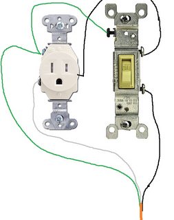
77KB, 564x714px
I know this isnt really ohm stuff, but does this look OK?
I want to control a shopvac with a light switch. Its dust collection on a saw, a control box will be very useful.
I bought a single outlet a single pole light switch, and a small box to mount it in. This is how you would wire it right?
>>
>>1068721
To make it clear, The orange wire is a cut up extension cord. And the shopvac would be plugged into that outlet
>>
>>1068725
As long as you don't overload the cord's amp rating, and you connect correctly around the terminals, it should be fine.
>>
>>1068725
as long as the switch socket and all wires are rated for the current drawn by the appliance you will be fine.
ideally the switch and cable should be rated for at least the socket maximum in case someone plugs in something else, otherwise label it CLEARLY and PERMANENTLY with the max current
if the box is metal you need to ground it and make sure you use a socket with a ground, otherwise (and ideally) use a plastic box.
in a 1st world country a fuse would be required
>>
>>1068706
what are the sense and set voltages for the opamp? what happens if you change them. do some debugging bro
>>
>>1068734
>>1068735
Well shit, I bought a 20amp socket because it was the only single outlet they had.
The switch is 15amp, and its a 16AWG cord which google says is good for only 13amp
My ShopVac says it pulls 8 amps on the website so it shouldnt be a problem, and its being mounted on the underside of my table saw so hopefully there isnt any chance of something else being plugged in.
Ill return the extension cord tomorrow and buy a thicker gauge one, and a fuse holder doesnt sound bad.
Would I just wire the fuse holder in line with the light switch?
>>
>>1068740
Nah dude, I've tried a few things already. making v select -5V instead of +5V by inverting it. having v select on both inverting and non inverting inputs while at -5V. And also at 5V. taking the Op Amp output and inverting it to use on the NPN. no avail.
I tend to be saddled with 9 - 10V no matter what, zero volts, or the one rare time where i got like 6 - 8V. Based on what i'm reading, emitter followers definitely have slightly less than unity gain so its a fool's errand anyway
>>
>>1068741
your socket is fine, your switch is fine, your cord is fine (16-gauge is what pretty much all heavy electrical tools use), and you dont need a fuse, coz you already have a breaker.
>>
Are PIR detectors directional if you take the refractor dome off them?
>>
>>1068985
of course, which is why the dome is necessary: to make it useful in a wide arc.
>>
>>1068988
Thanks for confirming, going to drive and get one right now.
>>
File: is transistor ded.png (5KB, 339x336px) Image search:
[Google]

5KB, 339x336px
I got a 2n 2219 that may or may not be broken.
I hooked it up like in pic related but the LED doesn't light up. Should I try with a lower resistor on the base or is it ded?
>>
>>1069048
I don't know the specs of the BT but assuming its not some very special part I think your circuit should work... maybe also check out whether the LED is ok. If you have multimeter with diode test, test it to look at the LED and also at the diode between B and E of the BT (it should read 0.6V or so).
>>
>>1069052
I tested the LED before and after. It's fine.
As far as I know the 2n 2219 is comonly used for switching up to 800mA.
>>
>>1069048
Pretty sure it's dead, you'd only need a beta of ~20 to saturate, and it should be at least 50 at that point.
>>
Can I use a 1:1 transformer to clean the output A modified sine wave inverter? I have a microwave transformer I can rewind with 0/1 or 0/2 gauge wire
>>
>>1069048
take a wire and short the collector to the emitter. if the LED stays dark, you have it in backwards.
>>1069097
the steel core will not pass high-frequency harmonics, so it'll clean it up a bit, but you gotta use thinner wire, maybe 100 turns, or your inverter will be overloaded. you can probably get the same effect wiring iron-core coils in series with the output wires. they'll be act as low-pass filters.
with enough filtering, you can turn any waveform into a pure sinewave, but it'll be costly in parts and in power loss.
>>
>>1068908
are you using the schematic i posted or you original? there is no emitter follower in the one i posted...
>>
>>1069150
cool, i have another input coil from another mot and i believe them both to be 100 turns or so. tell me more about winding an iron core coil, im down for a bit of diy to make sure i dont fry my electronics in a hurry. i really only need it for my home gas boiler since i dont wanna damage it if i run it on inverter power when an outage happens.
>>
File: chinkuino.jpg (79KB, 800x800px) Image search:
[Google]
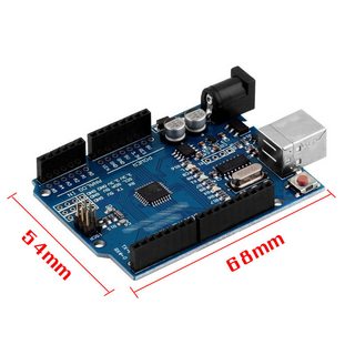
79KB, 800x800px
There should be no issues getting cheap "arduinos" from china right? Considering they are just overpriced breakouts for AVRs it should be pretty hard for a anyone to fuck it up I hope...
>>
>>1069176
also what kind of current can i push through the transformer and coil? its a 1500 continuous/1800 surge watt inverter
>>
>>1069183
I have 7 and they all work just fine. Make sure to eventually transition to "pure" AVR's though, its really rewarding.
>>
File: IMG_20161012_055224019.jpg (3MB, 4160x2340px) Image search:
[Google]
3MB, 4160x2340px
I do this.
>Raspberry
>Led Strip for indirect light
>Lcd to show Temp n forecast (later)
>Ds18b20 Temp Sensors
>Rrdtool (later) to keep Track of teneratures
>>
>>1069161
wrong terminology sorry
>>
>>1069188
>transition to "pure" AVR's
what do you mean by that?
do you mean buying chips and ditching devboards or dropping the arduino IDE?
I use the arduino ide, but mostly I just use cheap atmega8's using internal oscillator.
sll you need is a pullup resistor for reset and a 6 pin header for ISP
>>
File: Active load.png (24KB, 717x623px) Image search:
[Google]
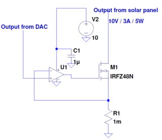
24KB, 717x623px
Working on controlling the output power from a solar panel. We use a nrf52 SDK which gives input to the DAC. Then we use a mosfet whith feedback to control the power drawn from the solar panel. The algorithm for controling the output power is already finished, but I am struggling to design a good active load, can anyone take a look at my schematics, and give som input? Would really appreciate it.
>>
>>1069188
>Make sure to eventually transition to "pure" AVR's though
So I assume there is some Atmel build-chan for using the chips directly. How does it compare to the Arduino IDE?
>>
>>1066447
Some kind of STM32?
>>
>>1069544
not sure what you're asking about, but if you wanna build an active load, google EEVblog #102.
>>
File: capacitor-filter.png (6KB, 369x180px)

6KB, 369x180px
Linear power source question
How do I calculate the filter capacitor?
>>
>>1069929
(5*Vmax) / (ΔV*2*pi*f*RL)
Where f is the freq. of the pulsating DC and ΔV is the peak to peak voltaje of the filtered waveform you want.
>>
>>1069910
Yeah, I'm trying to build an active load, but I'm not sure if I need to change the design?
>>
>>1069929
> How do I calculate the filter capacitor?
From the load current, mains frequency and desired ripple voltage.
Q=C*V => ΔQ=C*ΔV
ΔQ=I*ΔT
=> I*ΔT = C*ΔV
=> C = I*ΔT/ΔV
I is the load current, ΔT is the period of the rectified AC (10ms for 50 Hz mains, 8.333...ms for 60 Hz), ΔV is the desired ripple voltage. The larger the capacitor, the lower the ripple.
>>
>>1068596
no output at all?(measure with multimeter)
take a look at the diodes, varistors, fuses if any and the switching transistor.
>>
>>1069929
forget the bullshit answers above. the rule of thumb is 1000uF per amp of load current.
>>
>>1070031
> 1000uF per amp of load current.
That's 8.3V (60 Hz) or 10V (50 Hz) of ripple. IOW, it's probably far too small, even if there's a regulator after the filter (and definitely far too small if there isn't).
1000uF = 1 millicoulomb per volt = 1 amp-millisecond per volt.
>>
>>1070042
you're a silly calculator weenie. i've been designing electronics for longer than you've been alive.
>>
>>1070044
It doesn't matter how long you (claim to) have been designing stuff, you cannot change the laws of physics. Q=CV.
>>
>>1070112
also cant change the laws of stupidity.
example 1: 12V 1A supply, uses 1000uF cap -- http://www.circuitstune.com/2011/12/12v-power-supply-circuit-diagram.html
example 2: 12V 2A supply, uses 2200uF cap -- http://www.eleccircuit.com/simple-12v-2a-dc-power-supply/
example 3: 12V 5A supply, uses 4700uF cap -- http://www.circuitstoday.com/2-x-22-watt-stereo-amplifier-using-ic-tda-1554
look as hard as you want, almost everybody follows the 1000uF per amp rule of thumb.
do you supposed all those people, myself included, who've sat on benches surrounded by instruments for thousands of hours missed something that only weenie calculator nerds know about?
>>
>>1070154
Those circuits are all amateur junk. I doubt that any of them actually measured the ripple at the stated maximum current. Heck, I'm not sure that any of them even possess scopes.
Show me a circuit from someone with credibility, or actual full-load ripple measurements.
At least the first one will get away with it at moderate loads, due to the fact that the filter cap is followed by a regulator, and it has ~4V of overhead (12*sqrt(2), minus two diode drops).
I also highly doubt you have the experience you're pretending to.
Look: 1000uF/A = 1V/ms. No amount of hand-waving can change that.
>>
File: Clipboard01.png (36KB, 1920x1152px) Image search:
[Google]
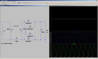
36KB, 1920x1152px
>>1070044
So point out the flaw in the simulation ...
pastebin: JCaVPYwb
>>
File: pioneer SA-9500.gif (45KB, 577x714px) Image search:
[Google]
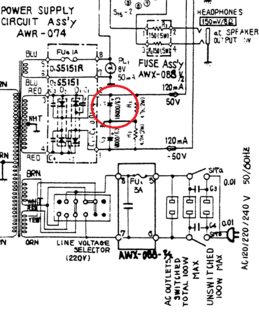
45KB, 577x714px
>>1070206
Pioneer stereo amplifier SA-9500, 100W per channel continuous power into 4 ohms. that's 5A per channel, or 10A for stereo, assuming the amp is 100% efficient, which is being generous. the rule of thumb would say they need 10,000uF, but this is Pioneer so they went for 18,000uF.
what does you wibbly wobbly calculator say is an adequate value? 400,000uF? 1 Farad?
>>
>>1070257
You're not showing anything relevant (i.e. what comes next).
For an audio amp, there'll be at least a low-pass filter and possibly a regulator downstream, which means that you can tolerate a fair amount of ripple at that point.
Your "rule of thumb" makes no mention of ripple voltage, in spite of the fact that the required capacitance is directly related to it. If you can tolerate a high ripple voltage, you can get away with smaller capacitors.
At 1000uF/A, you have to tolerate anywhere up to 10V (the exact figure depends mainly on the parasitic inductance in the transformer, which determines the duty cycle). With a 50V supply which is getting additional filtering, that's not a problem. For a 5V supply that's going to be used to directly drive logic, it's not even close.
If you're going to be giving out advice, you should learn to /understand/ this stuff, rather than trying to wing it using vague rules of thumb.
>>
>>1070268
the idea of putting a voltage regulator in a linear stereo amplifier is completely absurd. you're just showing massive ignorance by mentioning it.
and giving you an example from 1976 Pioneer stereo, when they were the kings of audio design excellence, isnt "winging" it, it's demonstrating best practices.
you still havent said what the wibbly wobbly says is the right value. is it above or below 1 Farad.?
>>
>>1070273
>wibbly wobbly
You are a fag. Just because you don't know the actual science behind something doesn't mean is wrong.
>>
>>1070154
The law of stupidity is your own projection. The laws of proven science trump that.
>>
>>1070044
Nice use of appeal to authority. You can make a claim of fake credentials and do not have to bck it up.
>>
>>1070298
>>1070303
>>1070305
>you don't know the actual science
what science? i'm defending a rule of thumb which has worked extremely well in millions of designs, and which i've seen with my own eyes works well enough in 1000's of circumstances. the calculator freak has nothing to offer except, ''well, it depends", which gets you nowhere. i'm still waiting for a proper answer on that stereo.
also, he screwed up here >>1070235
a 1.25A peak current would have merited a 1250uF cap, not 1000uF.
>>
>>1070273
> the idea of putting a voltage regulator in a linear stereo amplifier is completely absurd.
No, it's pretty common actually. Passive filters can reduce ripple, but only up to a point (too much inductance results in parasitic oscillation, and adding resistance for damping dissipates power). For digital circuits, a small amount of ripple doesn't matter. For audio, even small amounts can translate to audible mains hum.
> and giving you an example
... with anything relevant removed
> you still havent said what the wibbly wobbly says is the right value. is it above or below 1 Farad.?
It's in >>1069964
> => C = I*ΔT/ΔV
It's impossible to give a figure without knowing the maximum allowable ΔV (which is why any uF/A "rule" is bullshit).
For high current and low ripple, you have no choice but to use higher-order (i.e. L-C) filters or a voltage regulator, because otherwise you'd need capacitors the size of oil drums to get the ripple low enough.
C=18000uF, I=5A, ΔT=10ms (50 Hz supply) gives ΔV=2.8V, which might be tolerable on a 50V rail depending upon the amplifier topology (e.g. common-collector doesn't care much about supply voltage so long as you aren't hitting the rails, while common-emitter will couple supply ripple directly to the output).
(Note that it's a split supply; 10A total is only 5A per rail).
>>
>>1070311
> i'm defending a rule of thumb which has worked extremely well in millions of designs
You haven't seen millions of designs. And you don't appear to actually understand the ones you have seen.
> the calculator freak has nothing to offer except, ''well, it depends",
Because that's the correct answer. C depends upon more than just the current (although you can take ΔT=10ms as a given).
You realise that the person who designed that Pioneer amp actually did calculations, right? Even the people who design Cheap Chinese Crap do calculations (if only to figure out the absolute minimum they need to spend on the parts).
> which gets you nowhere. i'm still waiting for a proper answer on that stereo.
I'm still waiting for enough information to give one.
> a 1.25A peak current would have merited a 1250uF cap, not 1000uF.
It's 1A mean; the only reason the peak is 1.25A is .... the ripple. And an Increase of 25% is going to decrease the ripple by 25%, not eliminate it.
Or do you consider +/-3V of ripple on a 12V supply to be acceptable?
If you want stable DC, +/-3V of ripple means the unregulated supply has to be 6V above the regulator's minimum input voltage (i.e. output voltage plus drop-out), otherwise it's going to droop at the troughs.
>>
File: pioneer SA-9500(2).gif (77KB, 1116x661px)

77KB, 1116x661px
>>1070324
nothing relevant is missing. the +-50V goes directly to the power transistors. the 7M PDF service manual, is out there, but you prefer to cast aspersions.
from the pic, you can see the heat sink is already massive. adding a voltage regulator would have doubled its size.
no rule is bullshit when it works so well the best audio engineers use it.
>>
>>1070311
>what science?
The science behind how a fucking capacitor works you dullard.
>>
>>1070345
And you prefer to talk with knowledge you clearly don't have.
>>
>>1070345
>you prefer to cast aspersions
Get off your high horse. You resorted to childish name calling too.
>>
>>1070345
> nothing relevant is missing. the +-50V goes directly to the power transistors.
Which are all in common-collector (emitter-follower) stages, which aren't particularly sensitive to ripple on the supply rails (so long as you don't push the transistors close to saturation).
But the thing you keep missing is: they didn't pick those filter capacitors based upon some uF/A rule of thumb. They either calculated the allowable ripple then sized the capacitors to match, or they determined the size experimentally (i.e. change the capacitor values, measure the effect upon the level of mains hum, repeat until you find the point beyond which larger capacitors aren't worth it). There are three parameters which affect the required capacitance; current is only one of them.
If you wanted a 5V DC @ 5A supply for driving a logic board, those same 18mF caps would be nowhere near large enough unless you add an L-C filter and/or a regulator. Normally you'd use a regulator, but you still need enough filtering before that to keep the troughs above the minimum voltage yet minimising the average voltage to minimise power dissipation in the regulator.
>>
im loving this discussion guys. keep it goiing!
Thread posts: 364
Thread images: 73
Thread images: 73


